Georeferencing and Digitizing 1920 Sanborn Maps for Charlottesville, VA
John
Middendorf Lynx Geosystems, LLC
To georeference USGS DRG (NAD 1927 Datum) of the region, as well as an unreferenced aerial orthophoto (.SID format) of the area of interest (with NAD 1983 UTM 17N coordinates). In addition, we have jpgs of the Sanborn maps which will need to be georeferenced from scratch.
Because the orthophoto is more spatially accurate, we will use it primarily in the work that follows. The DRG will be useful to locate the region of interest in order to georeference the Sanborn .jpg.
Preliminary work -- ArcMap:
Locate region of interest:
Create Control Points in ControlPts layer (part of the geodatabase)
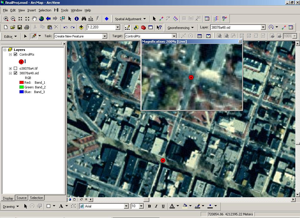
Above: Creating the second control point.
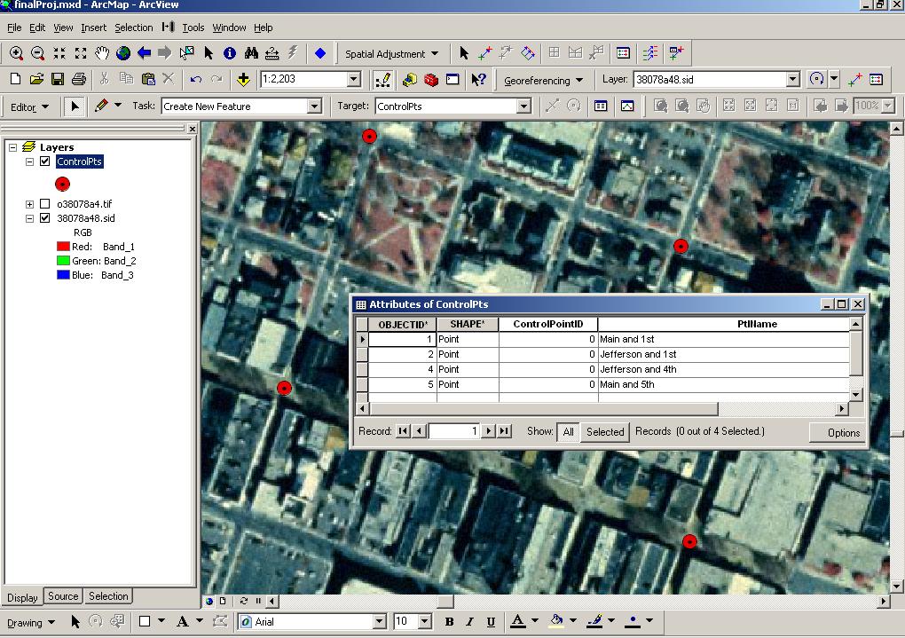
Above: Four control points created in ControlPts layer.
Georeference Sanborn Map
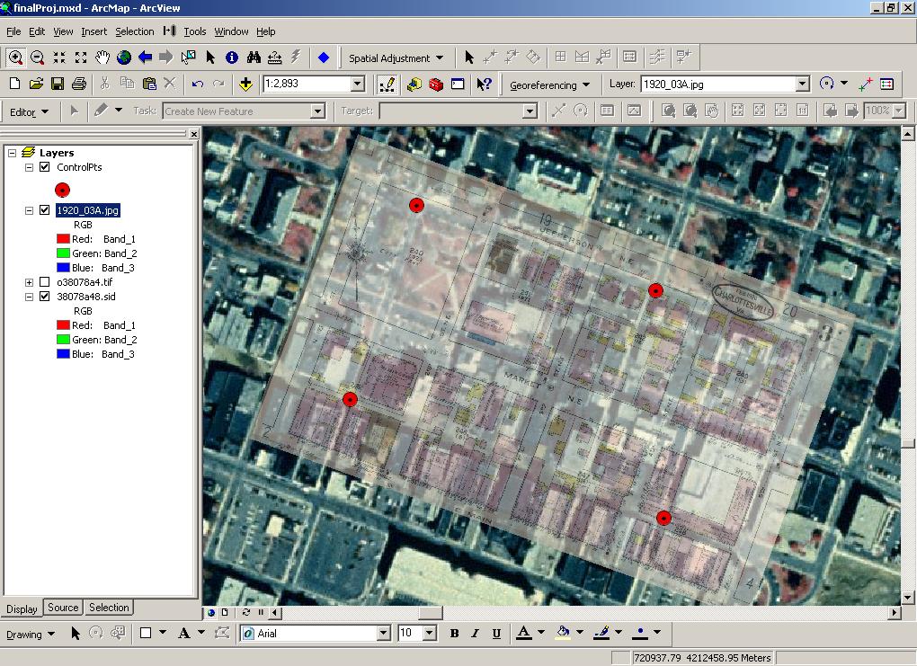
Above: after rotating jpg layer.
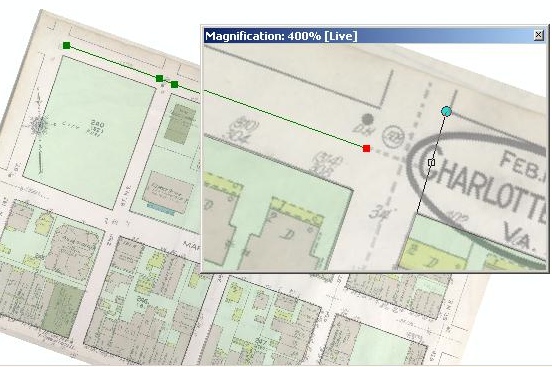
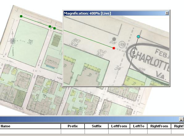
Using the 200% magnifier, link the intersections on the Sanborn .jpg with the previously created points in the ControlPts layer by clicking on the Sanborn layer first, then the ControlPts layer.
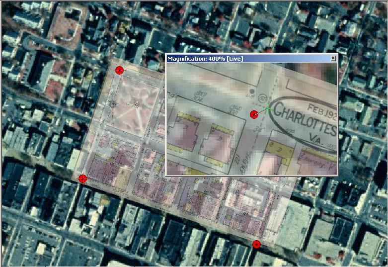
Above: creating third control point link using the magnifier and the Georeferencing Add Control Points command.
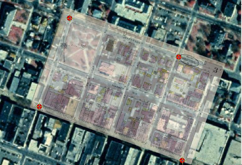
Above: all four control points linked.
Final Steps
Georeferencing this image required about 4 hours, but would only require 30 minutes to repeat the process. For a new map with all the preliminary work done, one hour would be adequate.
RMS ERROR
DISCUSSION
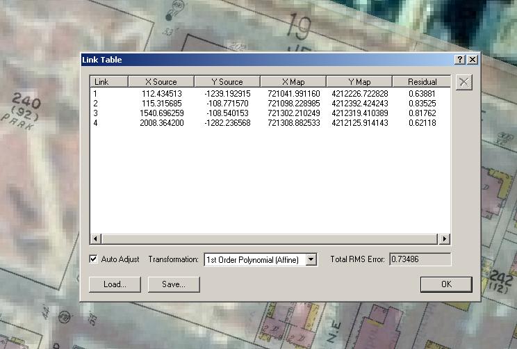
Screenshot: RMS error report from transformation link table of the 1920_3A.jpg to the georeferenced orthophoto.
The RMS error is not of diagnostic value because the control points on the Sanborn jpeg and the corresponding point on the orthophoto are visually estimated from ArcMap views. Neither point corresponds to an actual control point (one with known lat/lon coordinates).
DATA CHARACTERISTICS OF THE GEODATABASE:
Each feature class has the geometry properly spatial referenced with NAD 1983 Zone 13N projection, with X/Y domain extents as follows:
MINX: 717750 MAXX: 725452 MINY: 4208464 MAXY: 4216166 Precision: 278821.5586
Building features--polygons:
Roads--line
features
CityBlockLotsŚpolygon features
Used to outline the city blocks; it only has one additional field, ônameö.
ControlPointsŚpoint features
With ID and Name
fields.
For use in the
georeferencing transformation of the Sanborn .jpgs.
DIGITIZING THE SANBORN MAP
Step 3 involves digitzing building footprints and road centerlines in ArcGIS, using a georeferenced Sanborn map as a reference.Three hours was required for digitizing a single Sanborn map.
Digitizing is performed using the georeferenced Sanborn jpg as a background image. Snapping will need to be adjusted on a feature by feature basis. For example, if two buildings share a common wall, the edge snapping may be useful, or alternatively, the Auto-Complete Polygon tool can be used to close adjacent polygons in order to assure that the adjacent polygons share a single boundary line.
In addition, to make perpendicular lines and square corners in an editing session, after the first vertex, or after the first feature is entered, right-click to gain access to choices which include ôPerpendicularö and ôSquare and Finishö. The ôPerpendicularö choice work well with the ôCut Polygon Featuresö task. Also, and probably more functional, there is a Perpendicular flag under the Snap Options that allows a note to display when a line segment is perpendicular to the previous segment.
STREETS
Streets were digitized mostly using the Sketch midpoint tool, as seen below:
Road names, prefix and suffix (if applicable) were added during the digitizing process. After each length of road was digitized and attributed, the roads were split at each block for geocoding information. The direction of each streetĺs digitizing was performed from west to east, or from south to north for consistent FROM and TO direction.
BUILDINGS
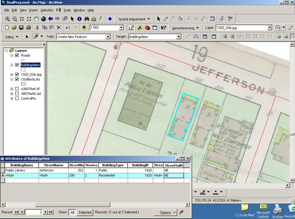
Buildings were digitized using the sketch tool and the magnifier to more precisely find the edges of each building. Attribute information was added immediately after each digitized record was created, as seen below:
When polygons share a
boundary the Auto-Complete Polygon is useful to assure that the
adjacent polygons share a single boundary line. Snapping settings and
tolerances were continually adjusted to align adjacent polygon
boundaries.
In order to create square corners, right clicking after the first vertex gets a list that includes ôPerpendicularö and ôSquare and Finish.ö I also investigated the ôperpendicular flagö under the Snap Options that allows a note to display when a line segment is perpendicular to the previous segment.
DATA ERROR
Data error while attributing and creating spatial features is inevitable. Good data structure and preparation is vital for minimizing data errors. In addition, checking data after editing is important.
Preventing Data
Entry Error
In order to prevent data entry error while
digitizing, the layout of the computer screen was important. I found
that entering the attribute data immediately after each polygon
digitzing was critical. Below is a typical workscreen:
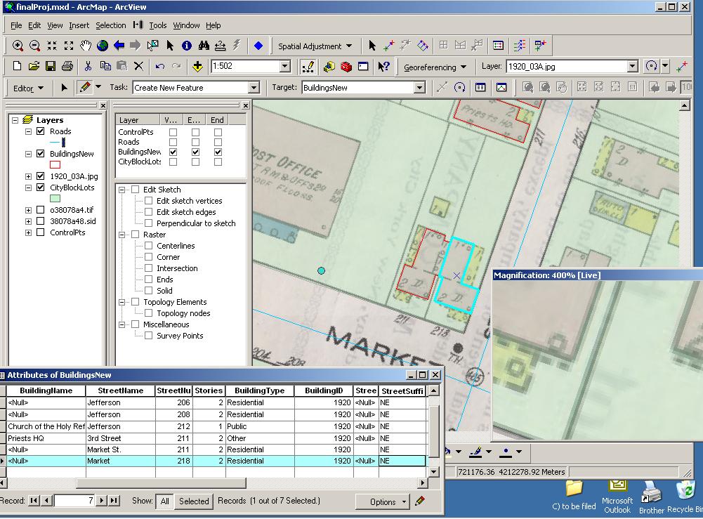
Using the magnifier and the above mentioned digitizing techniques allowed for reliable vertex entry.
Additional error prevention means:
- For attribute fields for which you are not employing a coded domain or a lookup table, you might create a document containing data entry standards, to be certain that each person is doing the same thing where there is a choice. (for example ST vs St vs St.)
Data Integrity Checking and Correction
To correct spatial data, the ÔÇťModify FeatureÔÇŁ tool is indispensable while in editing mode.
To check the attribute data, sorting the tables by various fields pinpointed some basic data entry errors. Using the select tool alternatively on the map and in the attribute table was also performed to verify results.
Additional data checking procedures:
CHECKING DIRECTIONALITY OF GEOCODED STREETS:
DATA MERGING
Using ArcToolbox, the provided Sanborn 3A street and building layers were merged with my feature classes. The street layer needed to be edgematched. This involved deleting records from 3A that were redundant, and using the modify sketch tool to link common roads.
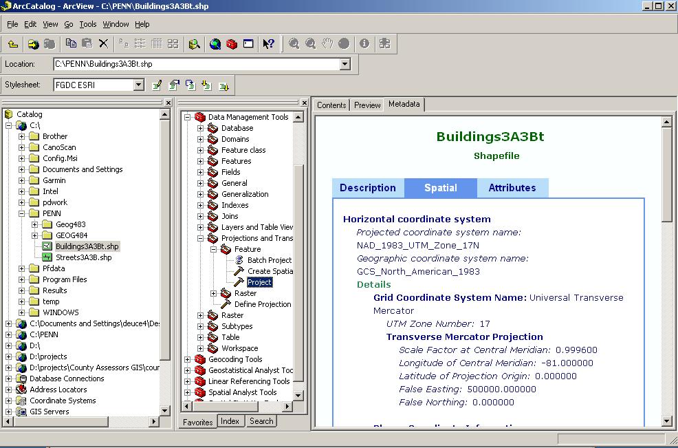
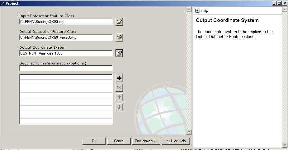
EXPORTING TO SHAPEFILES, CHANGING PROJECTION
This process was straightforward. I prefer the method of exporting feature classes from the geodatabase to shapefile in the same coordinate system primarily used (UTM), then, as a separate and more controlled process, going into ArcCatalog and performing a PROJECT operation to change the projection to the GCS system, as seen in the screenshots below:
Other methods for
changing the projection of a feature class in a geodatabase:
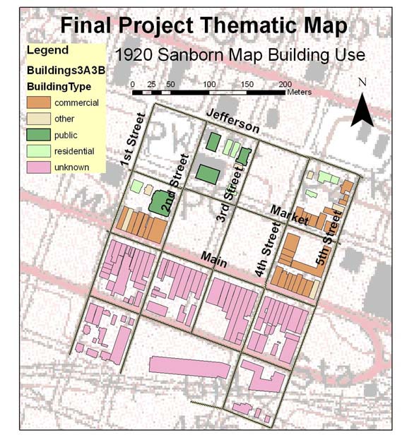
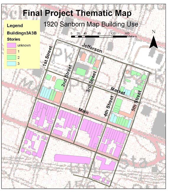
THEMATIC MAPS