by John Middendorf
Without a doubt, cams have revolutionized climbing. Ever since Jardine invented the first fully functional unit (with the proper camming angle) to the climbing community with his introduction of Friends, climbing achievement standards have advanced considerably through the use of superior technology. The way camming devices work is describable by basic engineering concepts. The principles of cams (more specifically, logarithmic spirals) described below are prerequisite to a functional camming unit design and use.
Logarithmic Spirals
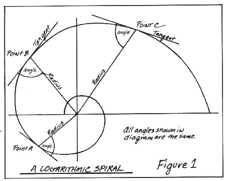
The modern camming unit utilizes the logarithmic spiral (also known as an equiangular spiral). The logarithmic spiral is a mathematical curve which has the unique property of maintaining a constant angle between the radius and the tangent to the curve at any point on the curve (figure 1).
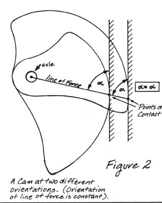
A logarithmic spiral cam (a "constant angle cam") ensures that the line between the axle and the point of contact (the "line of force") is at a constant angle to the abutting surface, independent of how the cam is oriented. Thus the force diagram for a given camming unit will be identical no matter how it is positioned in a crack, i.e. whether it be compressed or expanded (figure 2).
Friction
Camming units completely depend on the friction created between the camming unit and the rock. The force created by friction is best analyzed by understanding the engineering basic law of friction: the Frictional force is equal to the coefficient of friction (u) times the Normal (perpendicular) force (F=uN). For example, a 100 pound object with a coefficient of friction of 0.50 between the object and the floor requires 50 pounds of force to move it in a horizontal direction (0.50 times 100 lbs. equals 50 lbs.). The value of the coefficient of friction is determined by the materials and shapes (on a macroscopic level) of the adjoining surfaces.
Force diagrams
A force diagram is an analytical tool used by engineers to determine the individual forces exerted on an object or mechanical device. Vectors depict the forces and represent the inclination and magnitude of each force. The sum of all forces exerted on an object in static equilibrium equals zero, allowing us to calculate unknown forces. Figure 3 is a force diagram for an opposed 2-cam unit (here we define Y' as the constant camming angle). Here, the vector sum of the two side forces and the pull force equals zero. Each side force vector can be represented by two perpendicular vectors, the horizontal component, N (the outward force) and the vertical component, F (the frictional force). The horizontal and vertical components of the side force are related both geometrically (F = N times the tangent of Y'), and physically. The physical relation stems from a basic law of friction explained above. Combining these two relations allows us to pinpoint the factors involved in the holding ability of a camming unit.
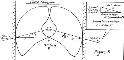
Force diagram analysis (figure 3).
S1=S2 (sum of horizontal forces)
P= 2F (sum of vertical forces)
Note that 2F must be greater or equal to P, the pulling force, for holding to occur. Each side force contributes one half to the overall upward component (the holding force).
Geometric relation: F=N tanY'
Law of friction: F=uN
Combining above equations and simplifying, we arrive at the relation u>tanY' for holding to occur.
Restated in plain English, this relation tells us that the coefficient of friction (u) must be greater than the tangent of the camming angle (Y') for holding to occur. Thus, if the trigonometric tangent of the camming angle is greater than the coefficient of friction, the camming unit will pull out of the rock under load.
Coefficients of friction
The coefficient of friction (µ) can be determined experimentally between two materials. A good general design figure determined empirically for the coefficient of friction between aluminum and rock is 0.30. Some types of rock have a greater coefficient than this with aluminum; the sandstone coefficient,however, is sometimes effectually less due to thin shear planes of the large grained, loosely cemented sandstone crystals, which explains the occasional failure of camming units in sandstone cracks. A good deal of experimental research could be done on the coefficients of friction between cams of various materials and surface characteristics and various rock-types (including icy cracks) under load, allowing cam designers to optimize even further for varying conditions and rock types.
Range and Camming Angles
The camming angle utilized for the shape of a camming device determines the cam's range (that is, the cam's maximum/minimum size ratio), and the cam's holding power. A larger camming angle results in a more elongated cam (use CAM program below to see this visually). Range and holding power are inversely proportional. Increasing the camming angle of a single-axle camming unit increases the range but decreases the holding power. If the tangent of the camming angle (Y') exceeds the coefficient of friction (u), the cam will pull. Note visually that a camming unit placement in a downward flare effectively decreases the camming angle and thus decreases the holding power. The larger camming angle results in a cam with more range, yet requires a higher coefficient of friction to hold the same force. Modern camming units optimize range and holding power with cam angles near 14.5 degrees.
Draw your own...
The mathematical equation for a logarithmic spiral is R=beaØ. To draw a logarithmic spiral curve, plot points along the curve, and connect the dots. All you need is a calculator with trigonometric functions, and a sheet of graph paper.
In the equation above, R equals the radius of the curve at a given point; b is a scaling factor and can be chosen arbitrarily; e is the natural log (=2.718); a is 1 over the tan of the camming angle; and Ø is the angle of the radius (in radians). R and Ø determine points on a curve plotted in polar coordinates; for a given Ø , R can be calculated and the point (R, Ø) can be plotted. Alternatively, we can use (x,y) coordinates (allowing us to use normal graph paper) to plot points along the logarithmic spiral curve. The conversion factor of Ø from degrees to radians is: Ø(radians) = 2/360 x Ø(degrees). Pi () is equal to 3.1416.
The x and y values can be plotted and connected creating a curve as in figure 6. Once the curve is plotted, the axle hole must be drilled at the origin (x,y = 0,0); material must be added around the hole. To create smoother curves, create a chart with more values of Ø and plot more points. To create curves with differing cam angles, substitute the desired camming angle by varying a (a=1/tan of cam angle).
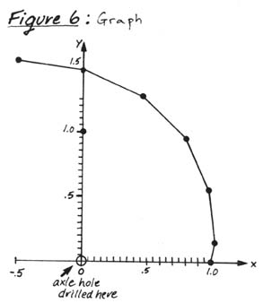
Figure 6
Determining camming angles of an actual cam.
It is possible to calculate the camming angle of an actual cam with two measurements of the length of the cam at two points 90 degrees apart (figure 7) Plug the two values of R1 and R2 into the equation on figure 7 to arrive at the camming angle.
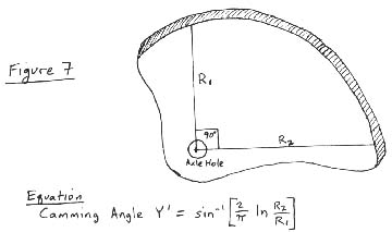
Figure 7.