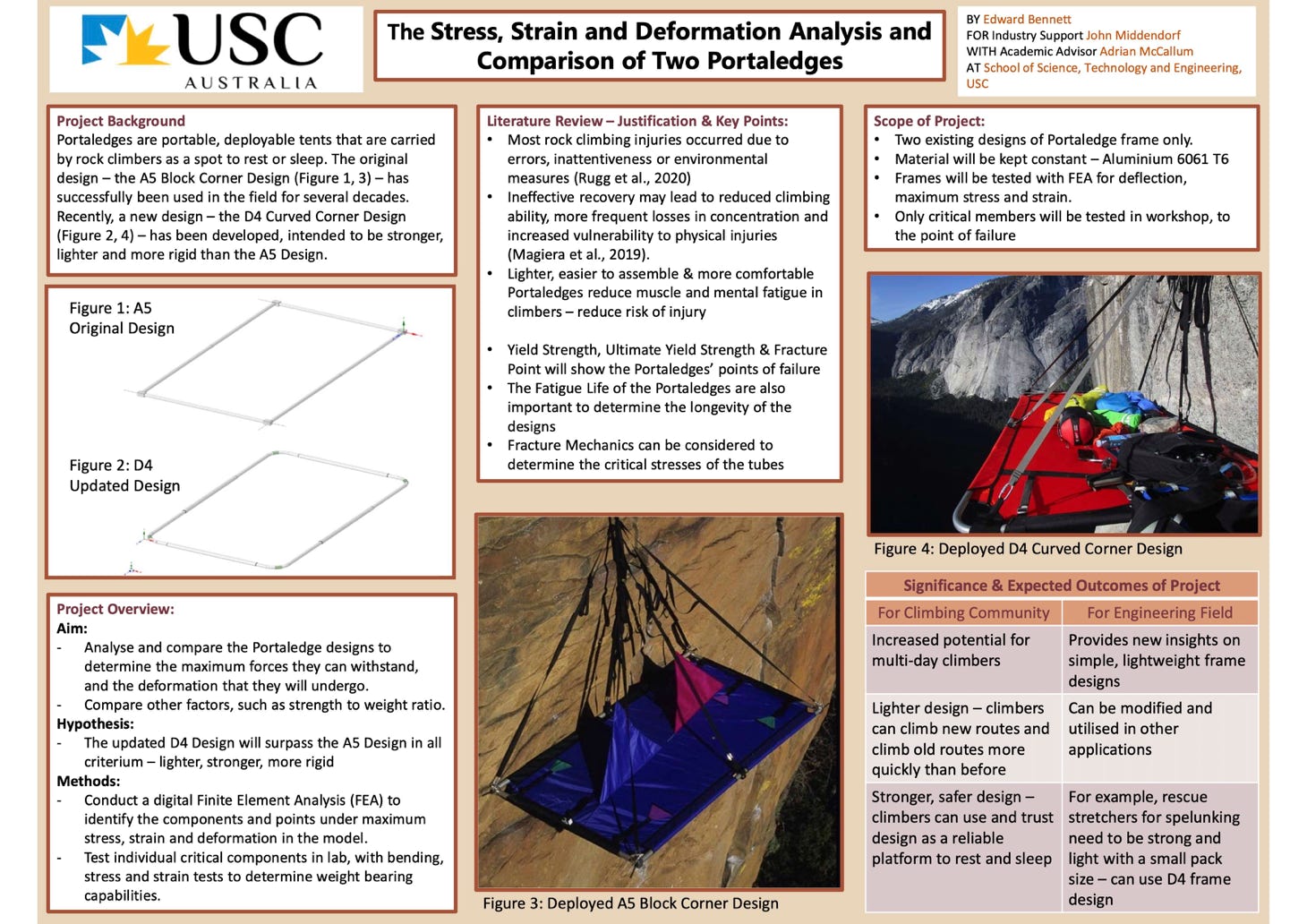
Engineering student Edward Bennett at the University of Sunshine Coast (USC) has performed a complete FEA analysis of two portaledge frame systems (2021).
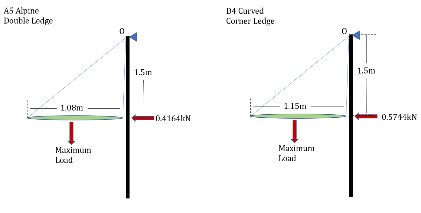
First, the two frame designs were modeled in CAD with all the components. Overall, the weight difference was less than 5%. The magic of the D4 system is having larger tube (1.375” 0.058”) in the areas of most stress (midpoints of long side), and though these larger tubes are a bit heavier, the lighter D4 joining system and curved tube corners vs. the A5 joining system, involving heavier 1” 0.083” tube, A5 block corners and eyebolts, the overall weight difference is only 130grams between the two designs.
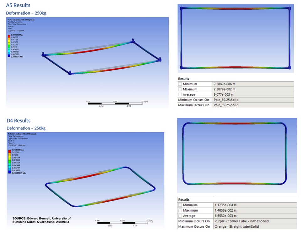
RESULTS—Deflection:
Here we see with an overall load distributed along the poles, the A5 flexes 2.2cm, while the D4 flexes 1.4cm, a 36% reduction in flex (note: real world deflections of both designs would be similarly proportionally bigger as the load is never as ideally distributed as in the FEA model).
The D4 frame flexes considerably less than the A5 frame for a given load. This result is applicable to any curved corner vs. right-angle corner system frame.
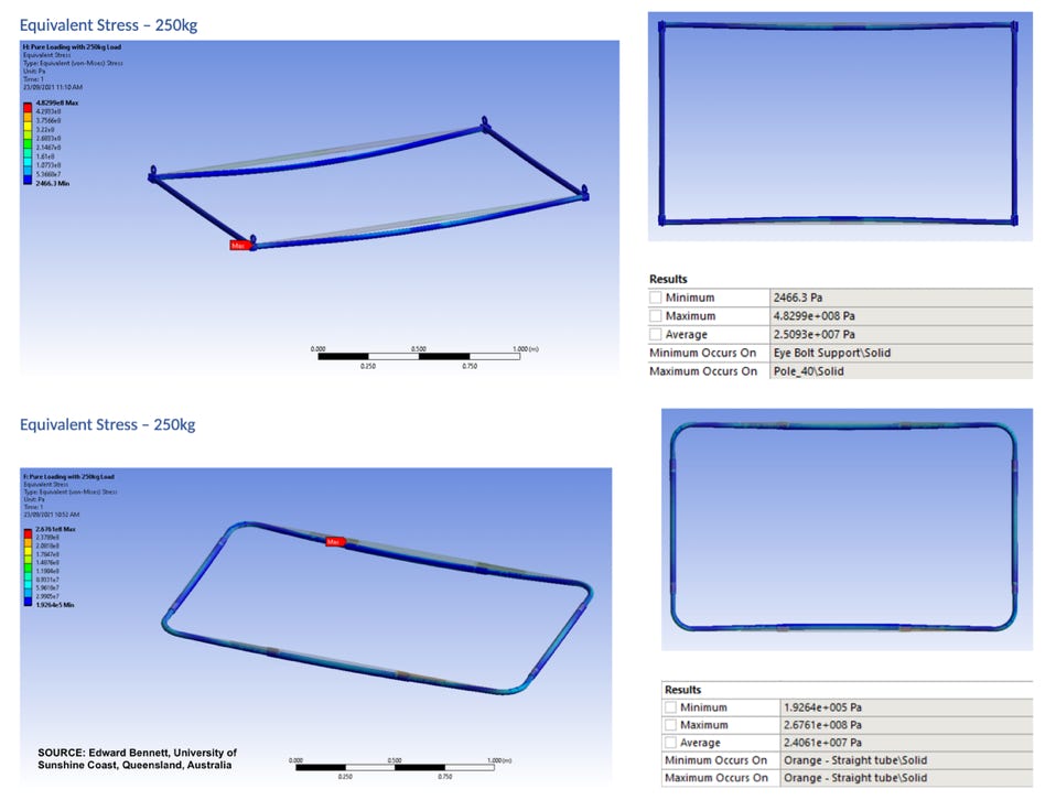
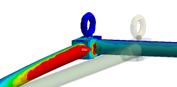
RESULTS—Stress:
The maximum stress in the A5 design with the standard load is 4.8e8 Pascals, with the highest stress at the A5 corner. In the real world, when this joint bends, it can sometimes prevent the ledge from being assembled properly. The D4 maximum stress is 2.7e8 Pascals, the maximum occurring along the long side. When this point starts to deform, the changed shape of the frame generally relaxes the stress, and the frame will not bend further unless the load is increased (and can be “unbent” in the field).
The D4 frame experiences a 44% reduction in stress with the same loading as the A5. This means the D4 frame can resist significantly more load for about the same overall frame weight.
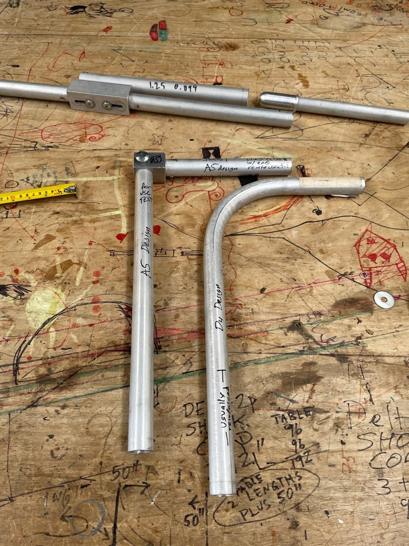
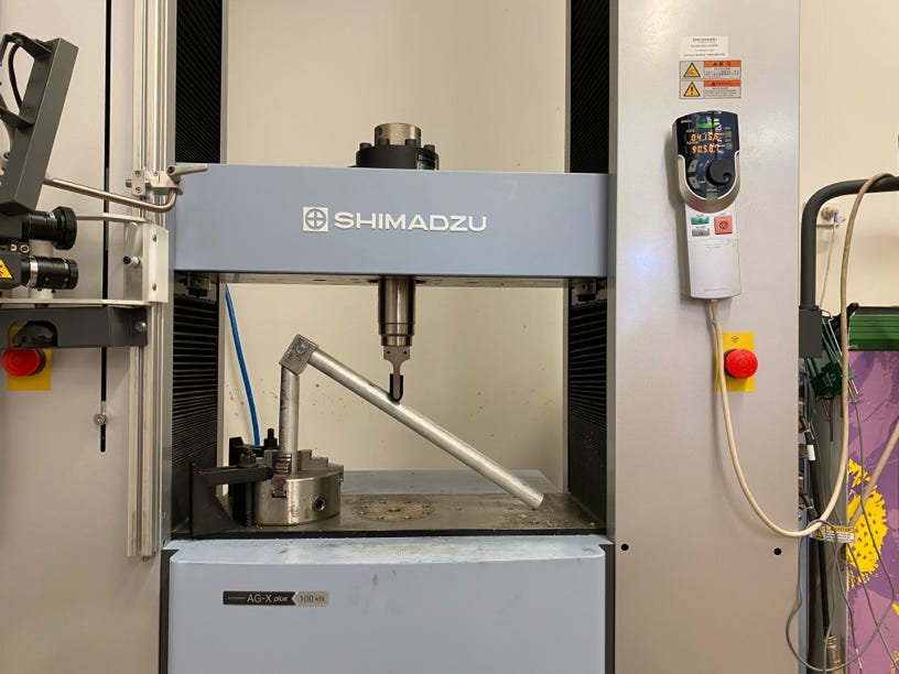
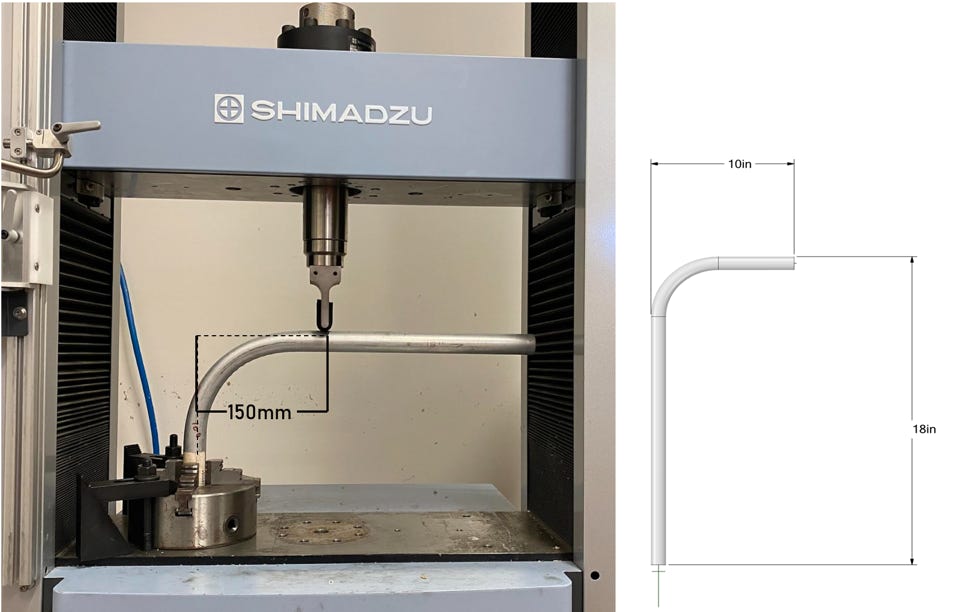
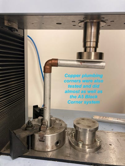
PART TESTING
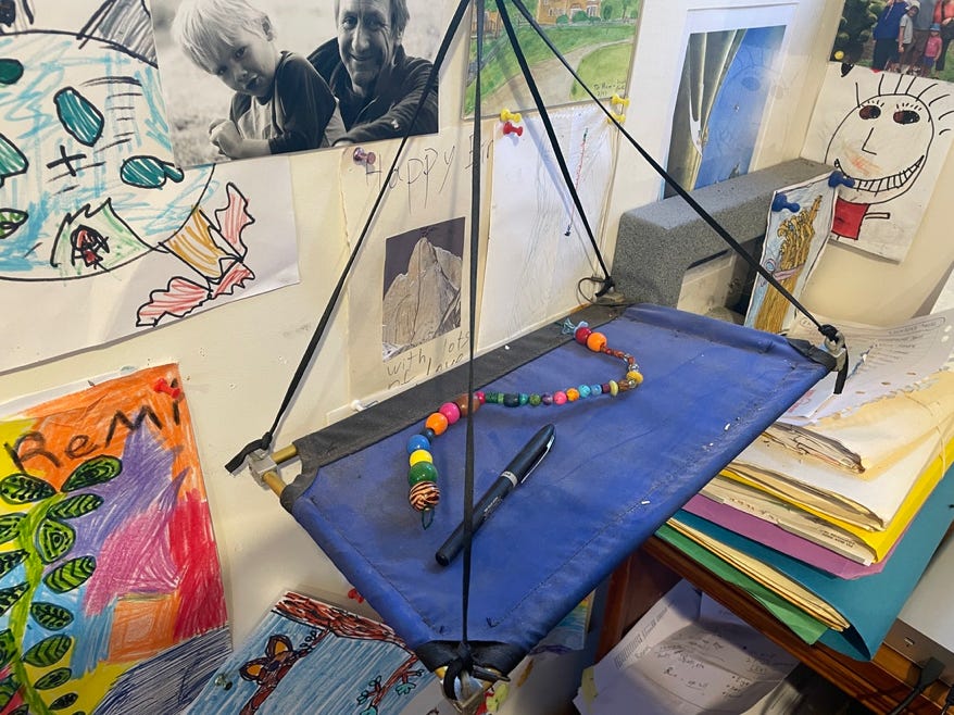
The next step in Edward’s project is to test some models of the joints using professional testing equipment, as well as some other portaledge corner/joint systems. This information will be useful to know for situations where the frame is not ideally set up with evenly adjusted straps (taco/no taco). Pic below:
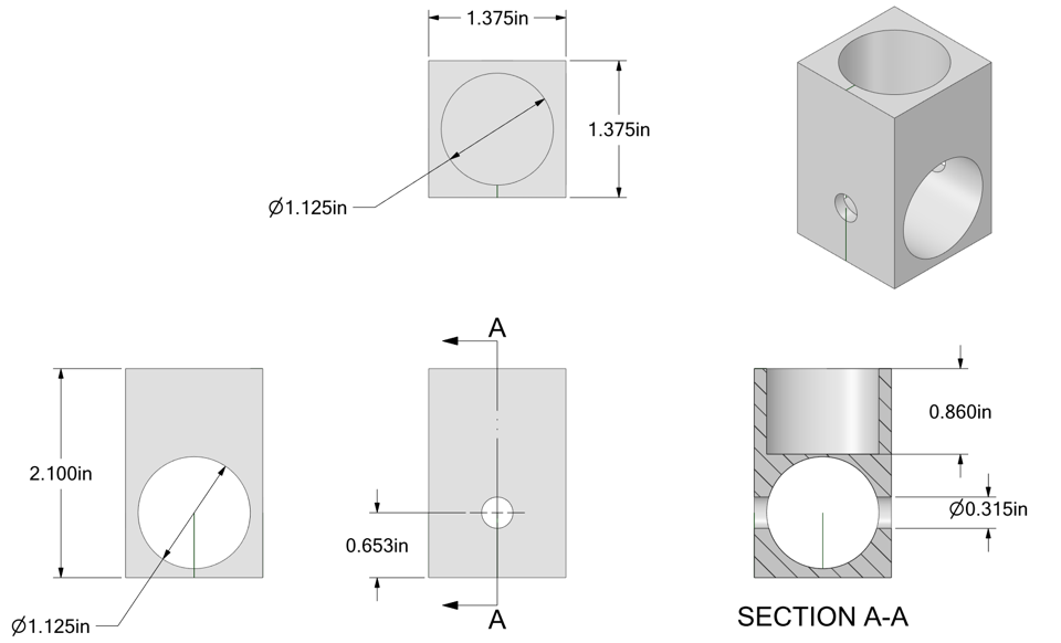
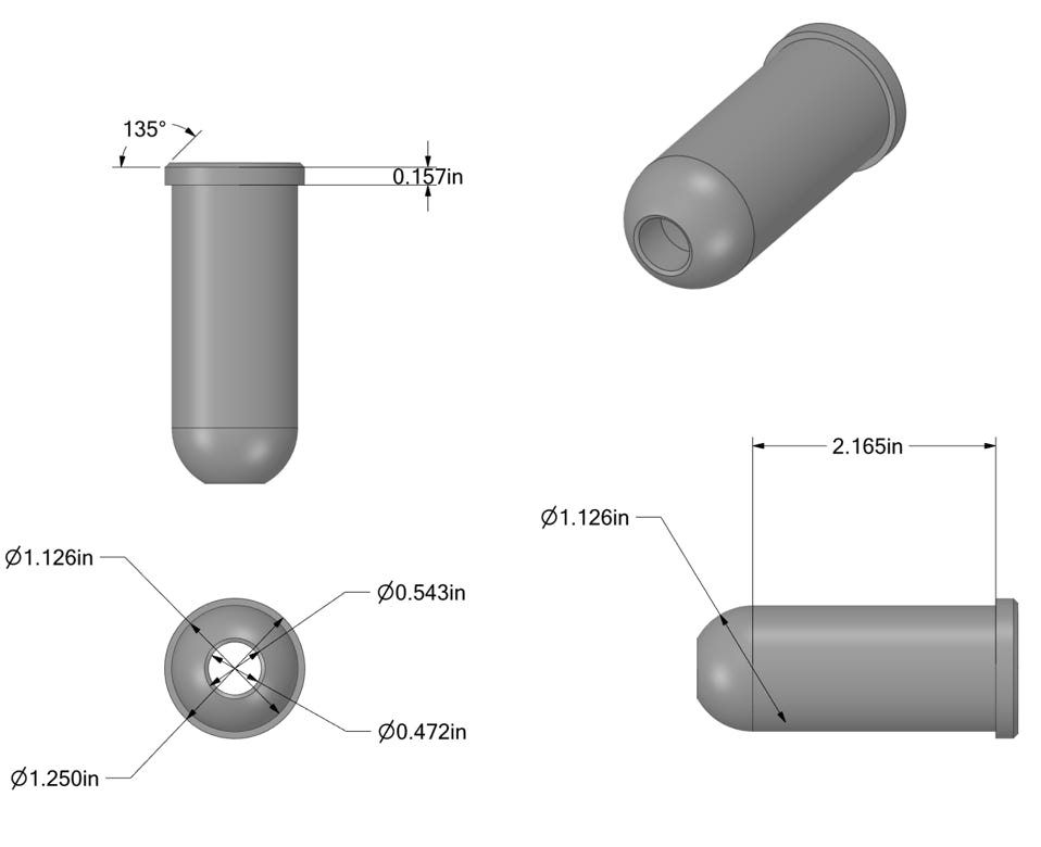
Photo-- left; A5 corner system. Right: D4 simple curved corner. Top: D4 joiner system, JM locking hinge design (2006) to be tested in beam loading.
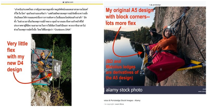
Other pics:
A model A5 I built back in Flagstaff. This model, with tiny A5 corner pieces that required precision milling, took about as long to make as a full-size portaledge.